
| home | articles | briefs | classifieds | flimsies | interchange |
|
|
||||||
|
|||||||
 |
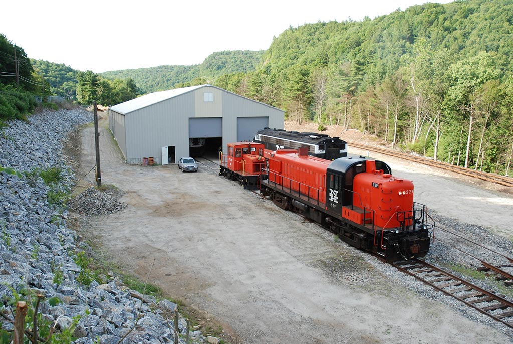
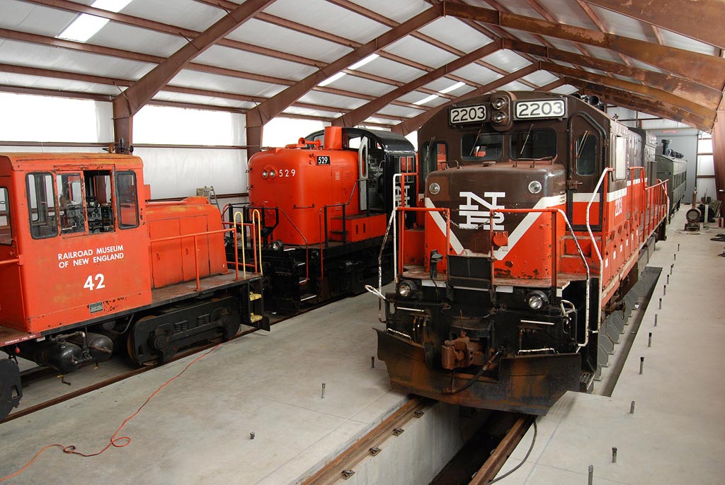
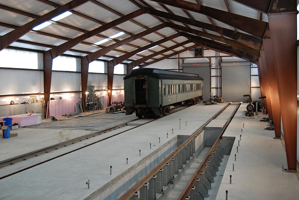
RyPN Articles September 14, 2007 previous article ~ return to articles index ~ next article Thomaston Restoration Shop After many years, Railroad Museum of New England (RMNE) volunteers finally have a building to work in. The 11,700 square foot restoration shop is nearing completion after seven years of planning and construction. With two through tracks, an inspection pit, wide work areas, good lighting, full insulation and heating, the modern 65 x 180 foot shop will enable restoration and maintenance work to take place year-round on RMNE's collection of vintage locomotives and cars. All that work has taken place outdoors up to now, with very little being done during the cold winter season.
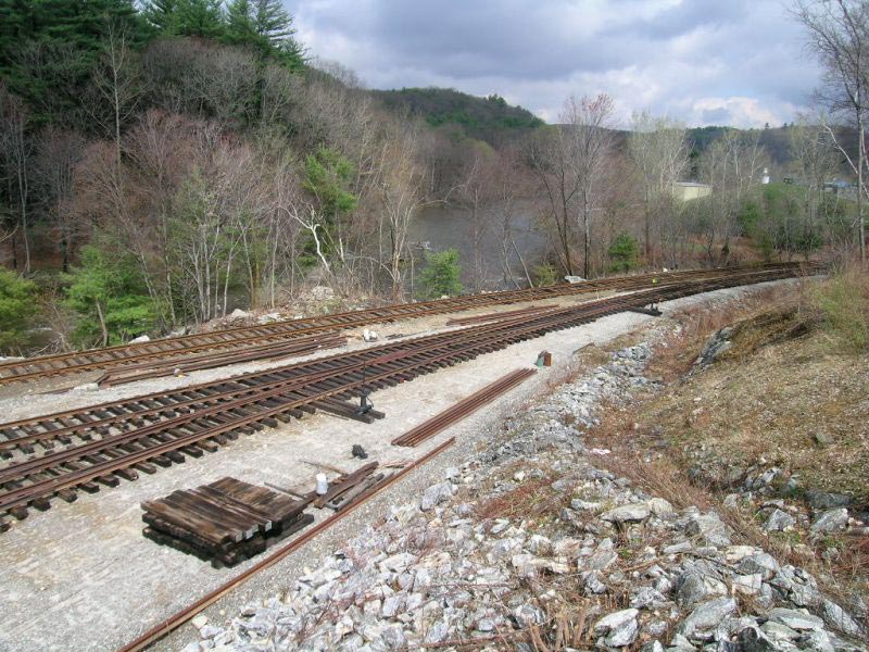
Planning for the shop project started in 1998, with tree and brush clearing of the 2+ acre site along the Naugatuck Railroad line operated by RMNE. Tremendous amounts of site work was necessary, such as rock blasting, rock crushing, top soil removal, culvert and drainage improvements, roadbed construction and site grading, to create a location for the shop building and space for a five track rail yard. The site had "ledge" (a quaint New England term for "solid granite in the way") in and under much of the area; this had to be exposed, blasted into smaller pieces, and crushed for track ballast and fill material. A new 1000-foot long roadbed was constructed as a fill next to the "Naugy" main track; this roadbed serves as the lead track to the shop site and yard area. To reach the shop building, almost 1500 feet of track and three switches were built by RMNE volunteers. Two more switches and another 2200 feet of track will be built as the rail yard on the site.
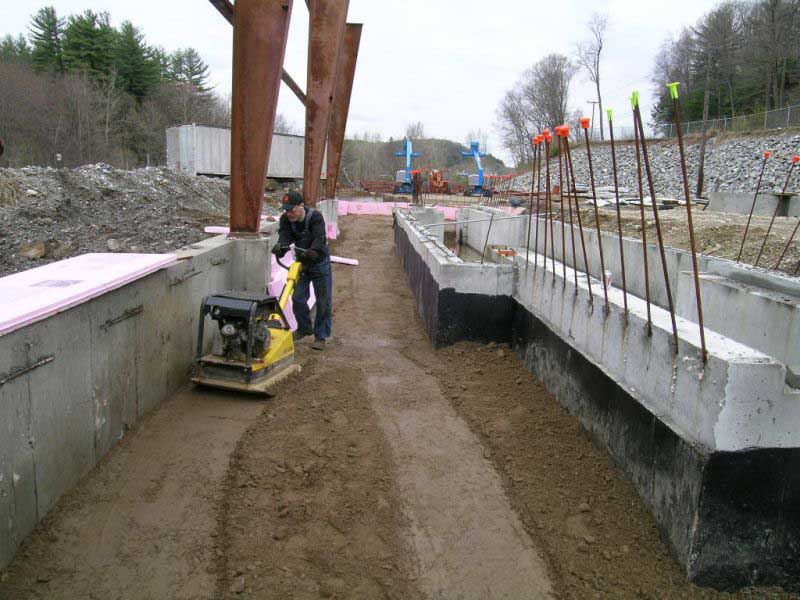
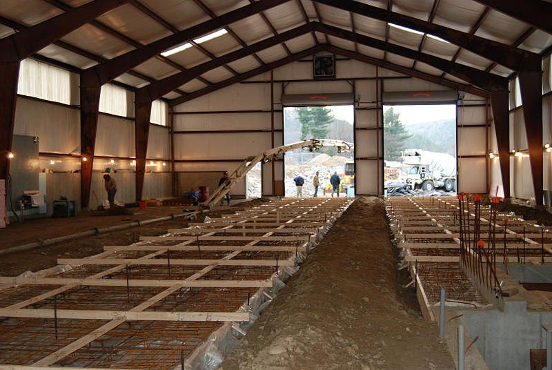
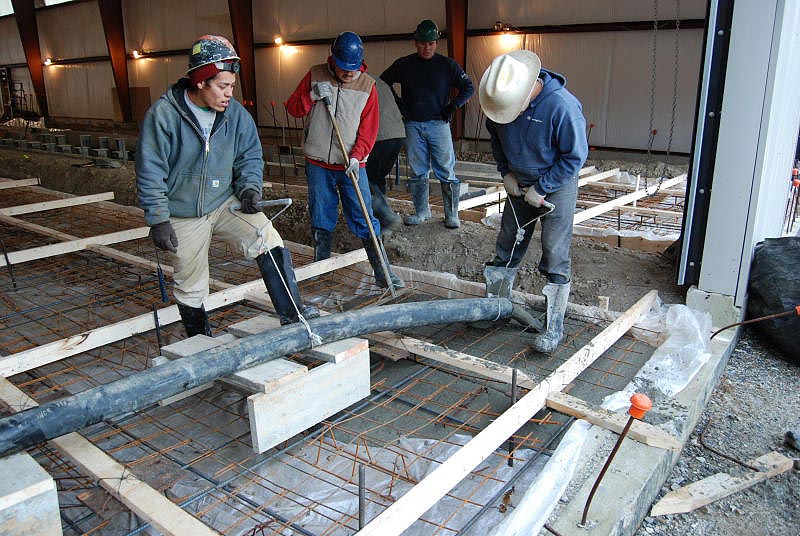
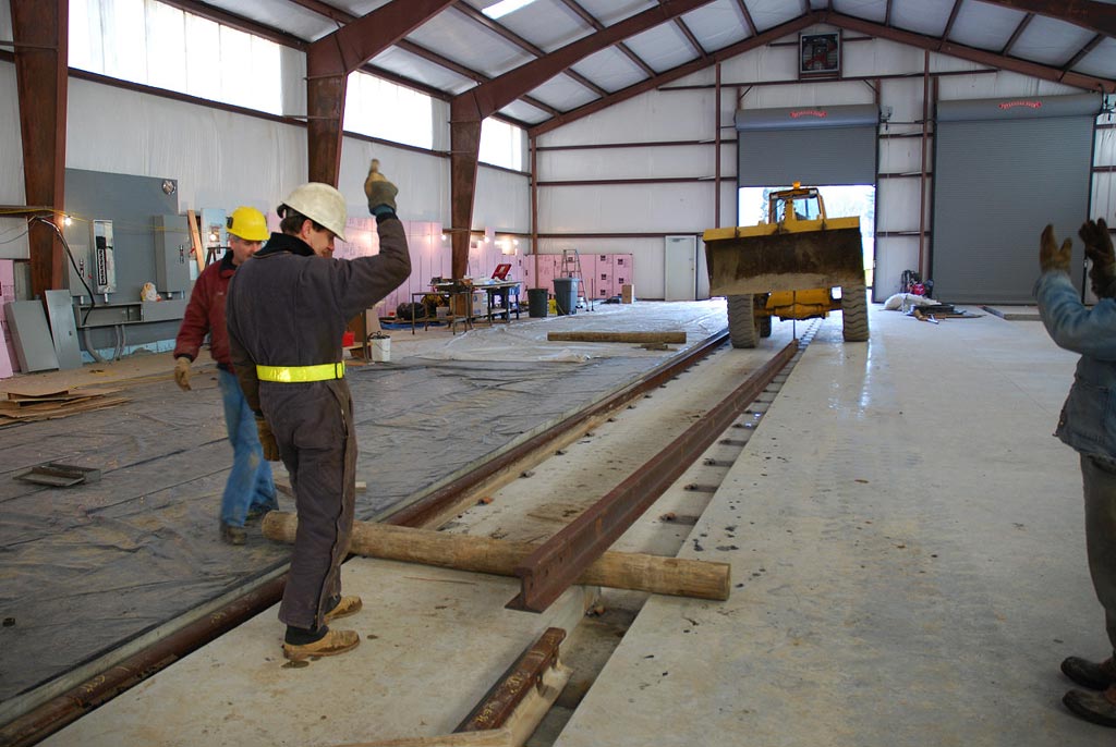
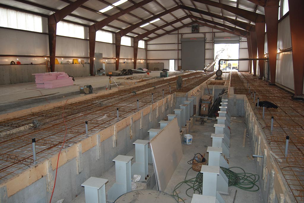
By Spring 2005, site work had progressed to the point where the building foundation was completed and the pre-engineered steel building was constructed. A 900-foot long lead track, mainline to shop lead switch and two yard switches were completed and the two shop tracks were now aimed at the north end of the building. Additional site work took place during 2005, including some utility installation. In 2006, the two tracks advanced to within 50 feet of the building, as the sub-grade in the shop was prepared. Many necessary but almost-invisible steps took place. A well was drilled for water service, and a septic system was constructed. Electric conduit and water lines were placed, inspected and backfilled (both inside and outside). The sub-grade was compacted and the concrete track slabs and concrete floor areas were formed and poured. The unseasonably mild weather in November and December 2006 (and January 2007) enabled the concrete work to continue right into the New Year, with the final bit of 340 cubic yards of concrete being placed in the floor on January 3rd. Work continued through February, even as outside temperatures dropped into the single digits. Previously, little was accomplished during the winter, but this year, the volunteers pushed the shop project forward indoors. With temporary heating, the building was easily brought to a comfortable 45-50 degrees, as Museum personnel carefully aligned and installed more than 640 welded track fasteners in the concrete floor. Others worked on installation of the permanent electrical service. By the end of February, the shop building was ready for installation of the rails, and the entrance of the first rail equipment. Work during March concentrated on preparing and connecting the shop track rails, with the east track seeing the first movement of a locomotive into the building on March 24.
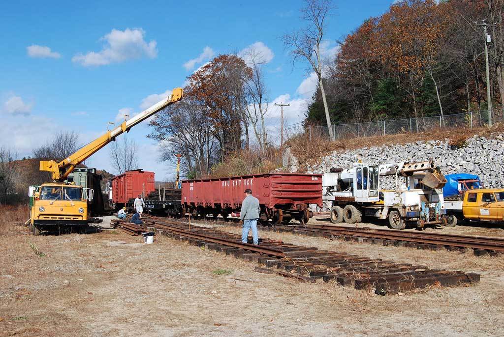
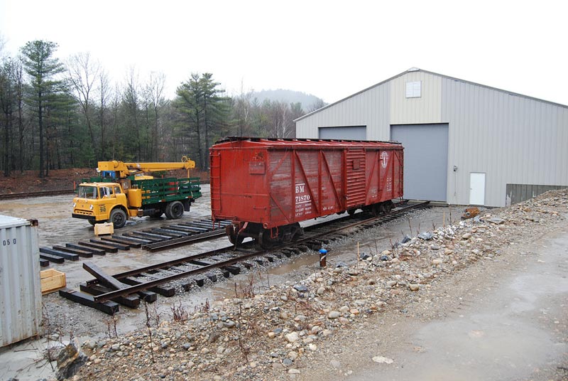
RMNE acted as its own general contractor for this project, supervising the experienced contractors handling such jobs as concrete forming and finishing, steel building erection, well drilling, rock crushing and some site grading. RMNE's own volunteers used Museum equipment to perform many tasks on the site, including most grading, almost all the soil compaction and backfilling, drain piping and electrical installation and material handling. Museum members brought their professional talents to the project - architects, electrical and mechanical engineers, heating and electrical contractors, heavy equipment operators, to name a few. And all railroad track and switch construction was done by RMNE volunteers. At the same time RMNE's members were working on this complex project, they were also running and maintaining a 19-mile railroad and the locomotives and cars to operate on that railroad. For example, over the last five years, in addition to the shop project, 2000 ties were installed on the main line, two small bridges were re-decked, a 600-foot long display track (and switch from the main line) was built at Thomaston station, in addition to the usual railroad maintenance tasks. Another major project took place during Spring 2006, as RMNE members carefully prepared 9 vintage freight cars for movement by highway, and moved them from Chester, CT to the "Naugy," where they went back on the rails. The new Thomaston Restoration Shop will enable RMNE's dedicated volunteers to work year-round in a first-class environment. Tools, parts and materials will be in one location. The yard tracks will permit the locomotives and cars located off-site to finally be in one place. There will be a place to clean up at the end of the day, and there will even be a small kitchen in the lunchroom-- some of the Museum volunteers are pretty good chefs, too!
Technical Details of RMNE's Thomaston Restoration Shop Shop and Yard Track
The shop lead track, yard switches, yard tracks, shop entrance tracks are all constructed from NH 107 rail. All-new switch timbers were used in the first three switches, with mostly relay 7x9 ties (some new 7x9s) in the track sections. Smaller rail sections (such as 80-lb) may be used in the south end of the storage yard tracks, as those sections will see little regular movement.
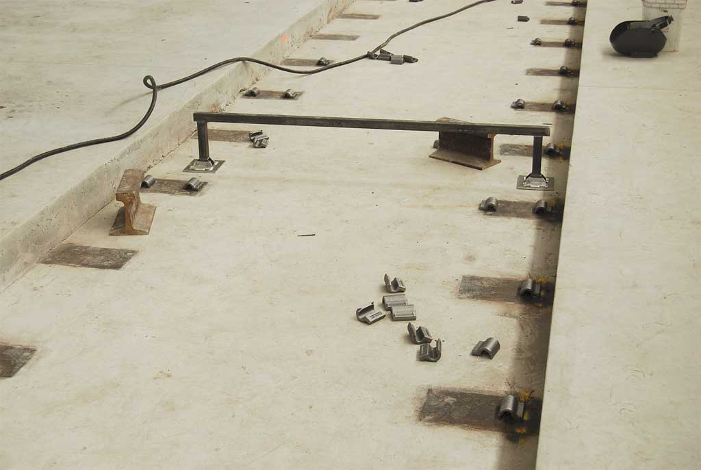
Concrete Floor and Track Slabs Each shop track is built on a 9-inch thick slab of reinforced 4000-psi concrete. The track fastenings are made from surplus 131-lb tie plates with two j-hook sections of 5/8" rebar welded into the shoulder side of the plate. 320 of these plates were accurately located and leveled along each track section as part of the form and reinforcing bar work before the concrete was poured. After the two track slabs were poured, the finish floor was formed, rebar installed and more 4000-psi concrete was poured for a depth of 7 inches. The design is such that a 24-inch wide, 16-inch deep jacking area runs the length of each side of both tracks. The finished floor is at rail head height, and there are center sections at each track door for rubber-tired vehicle access. Two center sections were poured in the middle of each track length, to allow shop equipment to cross over the tracks. Additional portable "drop-in" crosswalks will be fabricated, for use when needed.
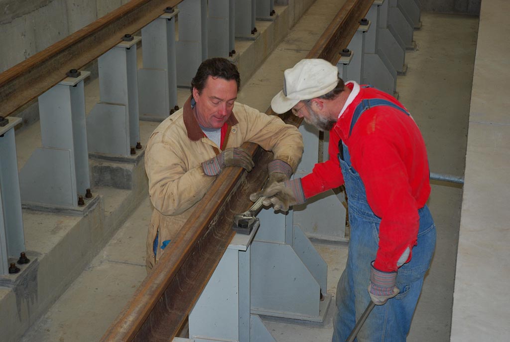
Once the concrete had cured and the forms were removed, cleanup of the floor area took place. The next step was to lay out and install two weld-on Pandrol shoulders on each of the 320 imbedded track plates. Some well-designed fixtures and jigs were made to ease the layout and welding process. It was still a tedious job, with two welders working at once. Over 50 lbs of welding rod was used in this step of the work.
The final step in the track work inside the building was to pull the rail in, connect joint bars, set the rail into the Pandrol shoulders, and drive the Pandrol E-clips to secure the rail to the floor structure.
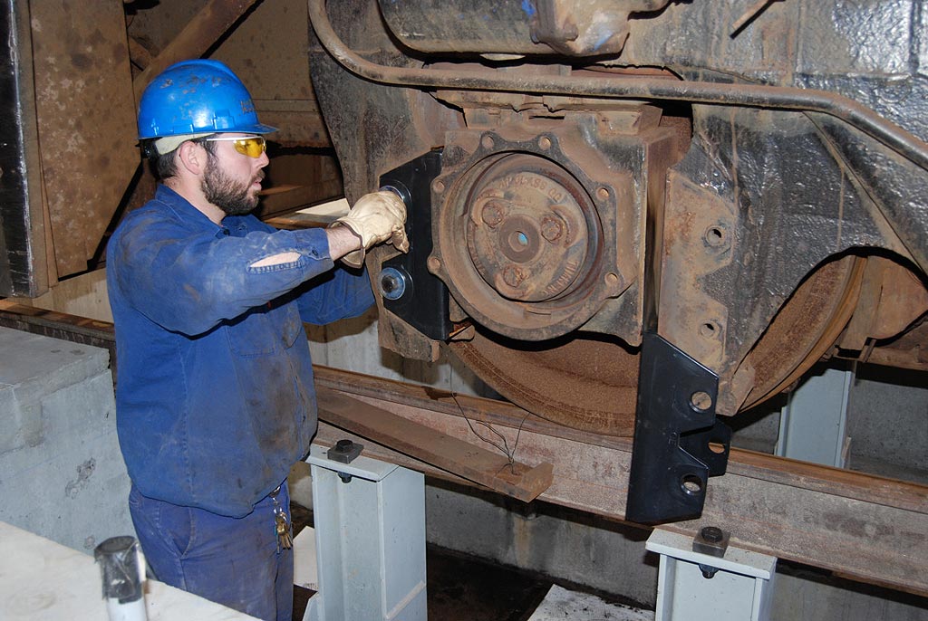
Inspection Pit
For the last ten years, RMNE volunteers have used a 20-foot long deck girder bridge over a former power canal (now dry), located about one mile from the Waterville yard area. All periodic inspections of locomotives required taking the locomotive and all tools and supplies that were thought to be needed, to the "pit bridge". Only one axle at a time could be accessed, and a simple inspection of a four-axle locomotive would usually take 5 or 6 hours.
Building Structure and Interior Arrangement
The four main track doors are 14 feet wide by 18 feet high, and are insulated steel roll-up doors, operated by 3-phase motors. Three personnel doors are also provided, one at each end, and one centered on the west side. The two tracks are on 20-foot centers, and they are offset to the west side of the building. This arrangement allows space for a 15-foot wide partitioned office and enclosed area along the east wall, without cramping the east side of the east track.
The partitioned area is laid out to use the northern 90 feet of the east side of the interior; it will be constructed using concrete block and metal studs. Work on this section will most likely start in Fall 2007. This area will contain, on the ground floor, a dispatcher's office, a lunch/break/crew room, two toilet/shower/washrooms (handicap-accessible), a mechanical room for furnace and water heater, a small air brake work room, and an enclosed tool crib. The second floor will house a Museum business office, a mechanical department office, and a record storage room. This two-story section will be heated independently of the main shop area. The rest of the east side area will be a wide work area, with room for some machine tools and other shop equipment in the 90-foot length. The structural steel framework of the building is being painted in a light gray color to help brighten the interior. Natural light is provided by insulated skylights in the roof, and by insulated wall lights at the top of each wall section.
Mechanical Systems Electrical power starts with a 400-amp 208 volt 3-phase entrance service from the street to the east side of the building. Distribution is from one main panel on the east wall, and a sub-panel on the west wall. Outlets for 110 VAC, 208 VAC single and 3-phase are being installed in the vertical columns along both sides. 110V will be on all columns, with 208 single and 3-phase on alternating columns. Lighting will be 25 metal-halide fixtures, which were donated (in excellent condition) by a local business. A number of fluorescent fixtures will be placed in the shop for use when the metal-halide fixtures are "warming-up". A 15-HP air compressor which RMNE has used for many years at our Saybrook Yard (and was originally from CNJ's Elizabethport, NJ shops) will be installed in a compressor shed outside the south end of the building. Air piping will distribute compressed air at each column on both east and west sides of the shop. Heating will be provided by natural gas-fired overhead tubular radiant heaters, totaling 850,000 btu. Five separate units will allow shop areas to be zoned, and programmable setback thermostats will be used for energy savings. For example, the setback stats will allow the shop heat to come up from an overnight 45 degrees to a comfortable 55-60 degrees by 8:30 on a Saturday morning. Water piping will be provided at each end of the building, adjacent to the track entrance doors, for water use outside the shop. A "laundry" sink is located in the main shop area, along the side wall outside the toilet rooms. A 175-foot deep water well is located 40 feet south of the building, and is piped into the south end of the shop. A concrete septic tank is located just north of the northeast corner, and supplies a sanitary field 150 feet further north. The roof gutters and six downspouts run into below-grade drain piping, terminating in a group of large concrete drywells, located underground between the mainline and western-most yard track.
Outside Areas
The vehicle access to the shop is via a driveway along the east side of the building. The currently-empty areas south and west of the shop building will contain yard tracks - the two through shop tracks will extend south for 250-300 feet, and the west side will have three tracks, each about 500 feet long. (Railroad Museum of New England - Howard Pincus) |
|||||||||||||||||||||||||||||||||||||||||||||||||||||
Copyright © 1998 thru 2025, all rights reserved, contents may not be used without permission. |