| Railway Preservation News https://rypn.org/forums/ |
|
| UP C-57 class consolidation backhead and piping https://rypn.org/forums/viewtopic.php?f=1&t=39614 |
Page 1 of 1 |
| Author: | frisco1630 [ Mon Jul 25, 2016 11:22 am ] |
| Post subject: | UP C-57 class consolidation backhead and piping |
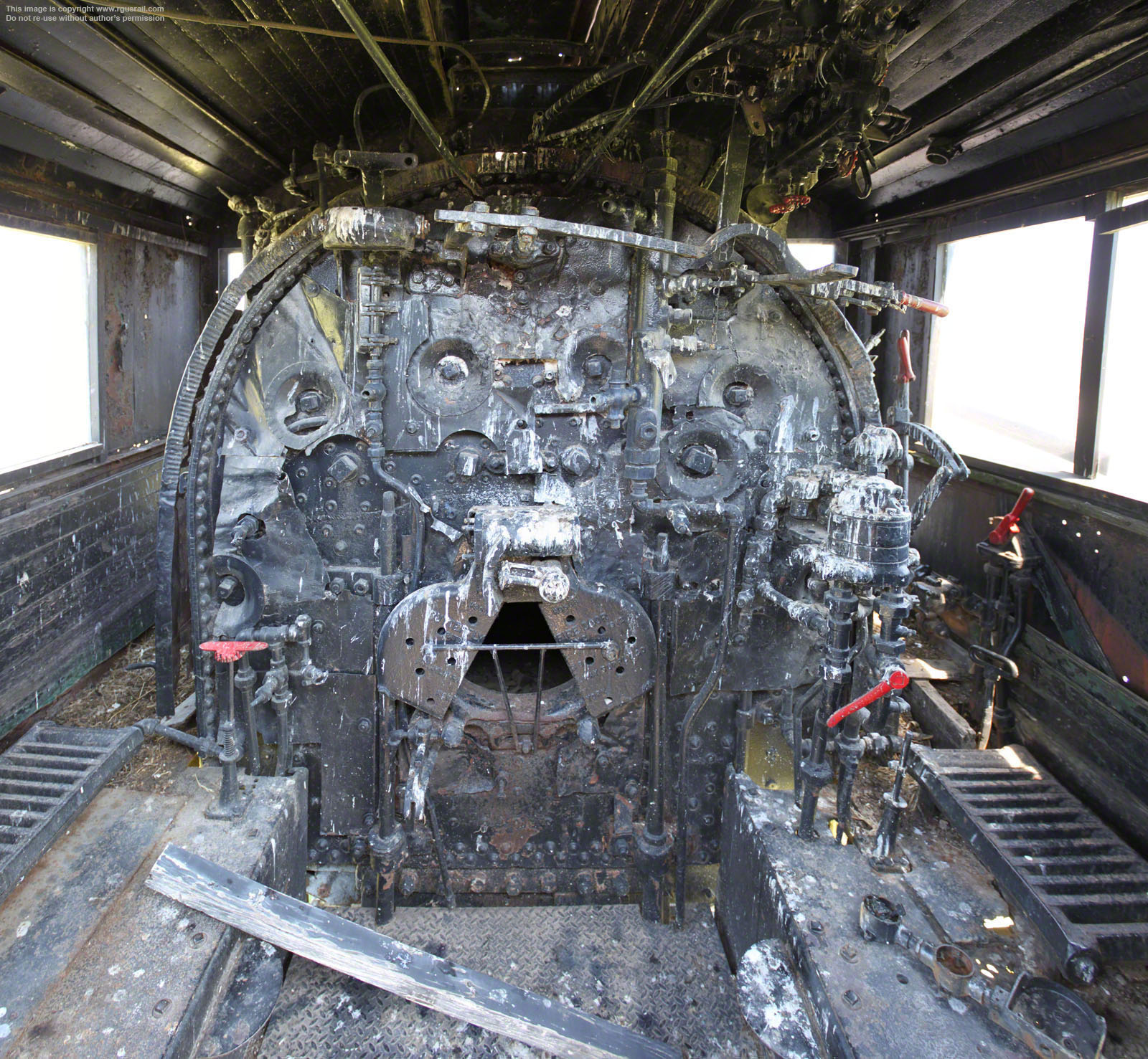
Hi All- We are in the middle of the long process of reassembling the piping and backhead for UP 428, a C-57 type consolidation. Unfortunately, we do not have many pictures of 428's backhead or external piping. The pictures that we do have are a bit fuzzy and unhelpful. Because of this, one of our volunteers has been refitting the piping via trial and error, a very inefficient process. Does anyone have any photos/diagrams of C-57 backheads or external/internal piping? |
|
| Author: | CBQ6323 [ Mon Jul 25, 2016 2:44 pm ] |
| Post subject: | Re: UP C-57 class consolidation backhead and piping |
I can get you pictures of some of the C-57s sitting in parks in Nebraska if that will help. Brad |
|
| Author: | frisco1630 [ Mon Jul 25, 2016 5:01 pm ] |
| Post subject: | Re: UP C-57 class consolidation backhead and piping |
That would be greatly appreciated...pics of the external piping and the backhead if you can see in the cab. Thanks! |
|
| Author: | ekrwy2 [ Mon Jul 25, 2016 5:08 pm ] |
| Post subject: | Re: UP C-57 class consolidation backhead and piping |
Will this help? http://www.rgusrail.com/album/neup437/up_437_16.jpg http://www.rgusrail.com/album/neup485/up_485_15.jpg |
|
| Author: | Dennis Storzek [ Mon Jul 25, 2016 9:58 pm ] |
| Post subject: | Re: UP C-57 class consolidation backhead and piping |
I have no idea if there is anything useful here, but this link just popped up in another discussion: http://utahrails.net/pdf/UP-Mechanical-Instructions_1947-1953.pdf |
|
| Author: | Randy Hees [ Tue Jul 26, 2016 9:35 pm ] |
| Post subject: | Re: UP C-57 class consolidation backhead and piping |
We have UP 624 at the Nevada State Railroad Museum in Boulder City... She has suffered in preservation, with her boiler separated from the frame when moved from Corrine Ut to Heber, then badly reinstalled... she is missing some valve gear, injectors and pistons. I can photograph anything on the locomotive you need. I will look through our files. For now our only plans for her are static display under a roof. Randy |
|
| Author: | John E. Rimmasch [ Tue Jul 26, 2016 10:04 pm ] |
| Post subject: | Re: UP C-57 class consolidation backhead and piping |
The truth of the matter is; Even if you had the pipe diagrams (which I do have but I am on vacation far from home), the drawings are really a "suggestion " more than they are a requirement. Infact, most steam locomotive pipe diagrams simply indicate a start and finish point with any rules related to where the pipe can be placed or not placed for other reasons. For example, if you study the superpower classes of the UP you will notice that even the boiler is made to accommodate certain pipes in specific places with the rest of the pipe designed for shortest possible run. The locomotive in question in this discussion could easily follow this rule of thumb rather than think each pipe has an exact place. Each pipe has a purpose more than it has an exact place. The blower has a defined start and finish point. The oil firing system had defined start and finish points. Piping is a matter of function and efficiency. Even if you had the drawings, they will not match perfect to what you actually have. Sorry for mistakes. Posted from my phone. |
|
| Author: | frisco1630 [ Wed Jul 27, 2016 1:33 pm ] |
| Post subject: | Re: UP C-57 class consolidation backhead and piping |
Thanks for the input John. That said, when you're back from vacation, if you could PM me the diagrams, I would greatly appreciate it...we can print them and put them in our library. |
|
| Author: | John E. Rimmasch [ Mon Aug 01, 2016 3:23 pm ] | ||
| Post subject: | Re: UP C-57 class consolidation backhead and piping | ||
As I am back at the office, I have looked up a few piping diagrams. This one is very generic in nature, but it proves the point. This one comes from the 1948 Locomotive Cyclopedia. I have on the shelf a number of pipe diagrams but they are all too large to scan on my printer. Suffice to say, they are all the same. For example, the C-57 class UP locomotives have in the files a document just like the one I have attached that says [paraphrased] "for all c-57 class, TTT, FEF and other equipped with......6ET air brake systems. Some locomotives may include two air compressors...." The topic of the thread is asking for exact placement of the pipes and pieces in the box that are left over. I am trying to softly point out that it never happened this way. The way it happened was....The shop took this shop drawing, the pipe they had, the pieces they had to include and they made it work. It was not an exact science that said...."You need 6, 8" pieces, 4, 12 inch pieces and you need 8 elbows and two 45 degree elbows. It was function, not form. Hope this helps.
|
|||
| Page 1 of 1 | All times are UTC - 5 hours [ DST ] |
| Powered by phpBB © 2000, 2002, 2005, 2007 phpBB Group http://www.phpbb.com/ |
|